Since its founding in 1970, the passion for racing has been at the heart of Sauber. Following its own Formula One debut in 1993, SauberMotorsport AG has established one of the few traditional and privately held teams in the sport.
Introduction
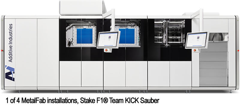
The KICK Sauber F1® Team are advanced AM users with many years of experience implementing the technology across their products with applications ranging from wind tunnel test parts, through to structural and non-structural race car parts and even pit crew support parts. To enable the fast paced production requirements of servicing a race team they have invested in 4 MetalFab printers, of which all are configured to enable continuous production and with a total of 8 AM cores, in which they are able to process multiple materials concurrently on each system including Titanium, Aluminium, Steel and Nickel alloys.
A great example of how the team have used their expertise to implement a structural application on their race car is the front suspension chassis inserts covered in this study.
Application Overview
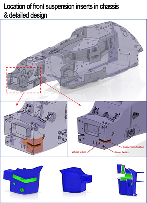
The chassis of an F1 car is the main structural component which houses the driver and from which all components, assemblies and systems are attached to. It is typically made from a lightweight but very stiff honeycomb composite sandwich panel structure. Where components of the car interface with the chassis (e.g. suspension, engine, coolers), chassis inserts are used to add local reinforcement to the composite sandwich panel. Depending on the function and level of stress acting, different materials can be used for the inserts from carbon and aluminium to very high strength titanium.
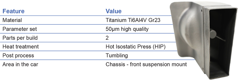
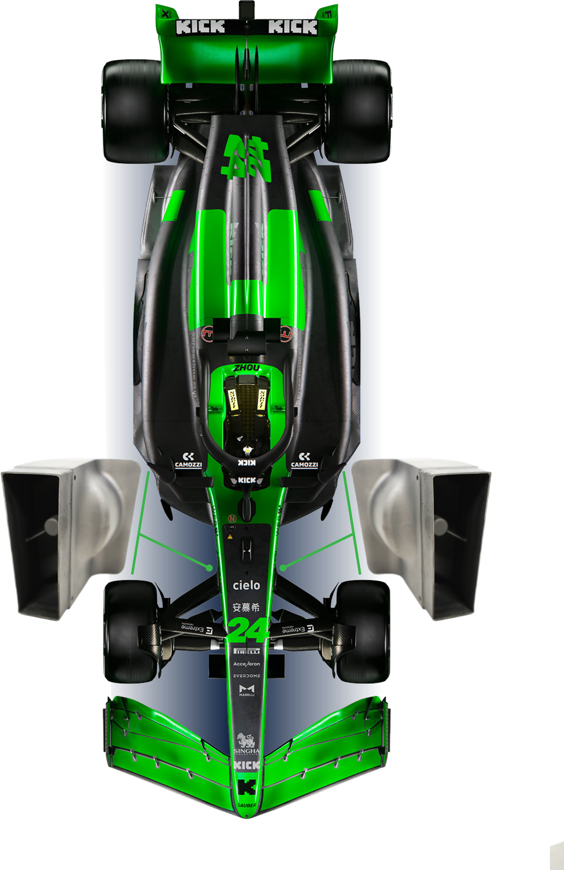
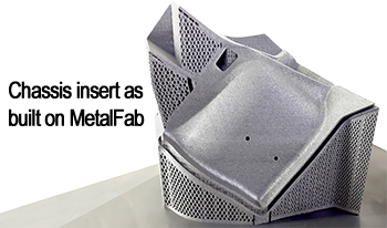
This case study showcases the design and manufacture of the two front suspension inserts on the Sauber C41 F1 racecar and are located in the front lower corner of the chassis. Their function is to accommodate the front suspension assembly fixation (lower wishbone and forward leg), but also to retain the wheel tether, to ensure the wheel does not become separated from the car in the event of suspension failure.
This Class A safety critical part(s), is additively manufactured from titanium (Ti6Al4V Gd 23) on the Additive Industries MetalFab system, to cope with the high fatigue and alternating loads experienced.
The inserts are designed to last the entire racing season, as they are permanently bonded within the laminate of the chassis. This equates to 200,000 cycles of design life with alternating suspension loads of 65kN tensile, and 30kN compressive. These chassis inserts are approximately 110x100x130mm in size, and weigh 580g each.
Benefits of AM with MetalFab
Previously, the chassis inserts were machined in multiple parts and assembled together, before being bonded into the chassis. Additively manufacturing the inserts, has enabled integration of these multiple parts into one component, drastically simplifying the assembly process. The design freedoms of AM, have also enabled an optimised ultra-lightweight design to be created, enabling undercut features, unconstrained by tooling access. Additionally, AM has removed the need for expensive and complex tooling during the manufacturing process.
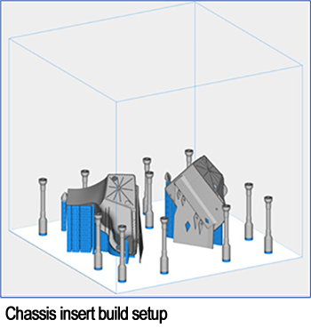
As Sauber are now fully utilising an Additive Manufacturing solution, a direct cost comparison to a machined version is challenging. However, on a previous race car (C36) iteration, the AM solution saved approximately 1800 Euro per insert, through component integration streamlining the manufacturing process. The large 420x420mm build plate size of the MetalFab, allows Sauber to build multiple sets of inserts in one build. The ability to print autonomously with multiple full field lasers on the system, allows production to be running unmanned over the weekend – a key requirement to realising the short lead time and agile production requirements for F1.
Sauber also benefit from the multiple core configuration available with MetalFab, allowing one build to start as soon as the other print is finished and beginning automated powder removal.
From a quality perspective, the inert atmosphere on the MetalFab also ensures powder is stored in a safe and inert environment.

Part Design Process
The chassis inserts have been designed to fulfil the full range of demanding load cases being transmitted from the wishbone suspension, nose push-off loading and wheel tether loads. Non- Linear Finite Element Analysis is used to accurately model the “real world” racing conditions on the part. This includes modelling the bonding between the insert and the chassis sandwich panel structure, ensuring the part and surrounding area are strong enough to withstand the demanding loading for the 200,000 design life requirement.
Many design iterations are completed, with the goal to minimise the weight of the part, whilst ensuring it meets the fatigue loading requirements for the design life.
Design for AM Considerations
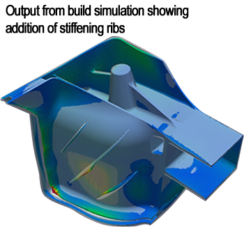
In conjunction with optimising the part design for functional use, design for AM considerations are embedded into the design methodology. The part is designed and orientated on the build plate to minimise the support structure needed. Build simulation software is used to simulate how the part will behave during the printing and heat treatment process. The thin wall geometry of the part makes it susceptible to unwanted distortion, and so stiffening ribs are added to ensure the part geometry is held in close tolerance to the original 3D CAD model, achieving the required surface profile tolerance.
Part Manufacturing Process
With the design phase complete, the part geometry is prepared for manufacture. Temporary support structure is added to the Chassis Inserts, along with tensile test coupons to monitor the quality of the build. The full field laser capability of the MetalFab, allows each chassis insert to be built with a separate laser, without compromising the quality of the parts. The parts are built using Additive Industries 50um Ti6Al4V parameter set, developed for our customers.
Following printing, the parts undergo a Hot Isostatic Press (HIP) heat treatment which acts to relieve the residual stresses from the printing process, reduce micro-porosity, and also optimise the microstructure of the components for optimal mechanical performance. Any temporary support structure is then removed, before the components complete a 2 hour tumbling process to further improve the surface finish.
Part Inspection
Each set of chassis inserts follow a strict inspection and quality assessment process before being released for assembly. A 3D scan of the inserts is performed to verify the part is within defined tolerances. Following this, material test coupons built with the components are tested to verify the mechanical properties. By adding these samples to every build, a database of data is created to not only assess the quality of one specific build, but provide an overview of the MetalFab printing quality throughout the machines life. The chassis inserts are then CT scanned to verify the parts do not have any significant internal defects that would compromise the performance. This is particularly important for safety critical class A components, such as the chassis inserts.

Component Assembly Process
With manufacturing complete, the inserts are assembled into the main car chassis. The inserts are bonded onto the cured outer carbon skin of the lower half of the chassis. The inner skin is then later laminated and cured over the top.
Component Testing
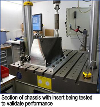
With significant part inspection and coupon testing already complete, the chassis inserts are then tested within the context of the chassis assembly to ensure they perform as required. This is done using a physical test rig, where a small section of the chassis assembly is subjected to static and dynamic loads mimicking the loads experienced during racing. By performing the tests in this way, the section of the chassis assembly is a direct representation of the race car, following exactly the same production process. Once the testing campaign is completed satisfactorily, the technology is then released to be used on race car for the season.
Conclusion
This case study has demonstrated how KICK Sauber F1® Team are using their MetalFab systems to create safety critical Ti6Al4V chassis inserts for their F1 race car. The design freedoms of AM have been leveraged to create an ultra-lightweight, integrated single component optimised for the significant loads imparted. The autonomous and full field laser capability of the MetalFab enables the demanding F1 production requirements to be met whilst maintaining high part quality.
